
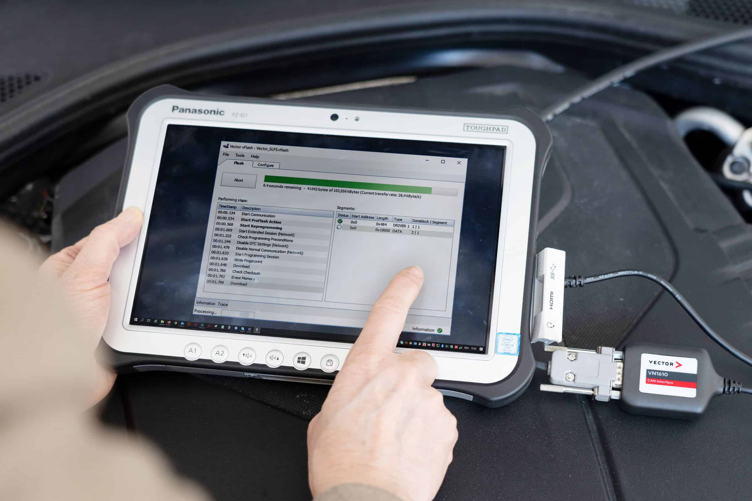
No single instrument can tell you whether an engine ECU has failed. The unit sits at the centre of the engine’s electrics, reading every sensor and switching the injectors and ignition, so each diagnostic technique sees only part of it: a scan tool hears what the ECU reports, a multimeter measures what reaches its connector, an oscilloscope shows how its signals behave over time, and a bench test examines the unit on its own.
This guide sets those techniques side by side: what each one measures, what it can and cannot reveal about the unit, and how to use it without doing damage. The order in which to run the checks, and what each result means, is covered in our guide to ECU diagnostics.
Four questions, and the technique that answers each
Much wasted effort on ECU faults comes from asking a tool a question it cannot answer. Every technique on this page answers one of four:
- Is the ECU talking, and what has it recorded? A scan tool.
- Is it being fed properly? A multimeter at the connector.
- Are the signals going in and out of it behaving? An oscilloscope, with live data alongside.
- Is the unit itself sound? A bench test, off the car.
The first three are on-car techniques, and mostly they clear or convict the circuits around the ECU. Only the fourth examines the unit in isolation, which is why it usually comes last. If you are still deciding whether the ECU is a suspect at all, start with the symptoms of a failing ECM.
ECU diagnostic techniques compared: what each can and cannot show
Read each row across. Every technique is strong in one column and blind in another, which is why a firm verdict on an ECU normally takes more than one.
| Technique | What it measures | What it can show about the ECU | What it cannot show |
|---|---|---|---|
| Scan tool: fault codes | Codes the ECU has stored | That the ECU is powered and communicating, and which circuit it has flagged | Whether the fault lies in the component, its wiring or the ECU; faults the ECU cannot detect |
| Scan tool: live data and logging | Sensor values as the ECU reads them, live or recorded on a drive | Implausible readings, including faults that appear only in certain driving conditions | Where a wrong value went wrong: sensor, wiring or ECU input |
| Scan tool: actuator tests | A component’s response when commanded on and off | Whether the command path and the component work together | Which part failed when nothing responds |
| Multimeter | Voltage, resistance or current at one point | Supply and earths at the connector, voltage drop, current drawn by driven components | How a switching signal behaves over time; brief dropouts |
| Oscilloscope | Voltage plotted against time | Shape, amplitude and frequency of input and output signals, and interference on them | Why an output is wrong inside the unit |
| Test board or breakout access | Nothing itself: it brings each ECU circuit out to a safe test point | Clean access to power, earth and output circuits without harming the harness | Anything, until a meter or scope is connected |
| Visual and connector inspection | Condition of casing, connector and pins | Water, corrosion, burn marks, bent or loose pins | Electrical faults that leave no visible trace |
| Bench test off the car | The unit powered on a rig and fed simulated inputs | Whether the ECU reads its inputs, drives its outputs and holds up over a long run | Faults in the car’s own wiring, sensors or supplies |
Scan tool techniques: codes, live data and actuator tests
Reading fault codes
A scan tool plugged into the diagnostic socket asks the ECU for the codes it has stored. The unit sets one when a signal it monitors stays outside its permitted range for long enough, so a code points at a circuit rather than naming a failed part.
The most useful thing a code read proves is often the simplest: the ECU answered. A unit that communicates has its power, earths, processor and basic functions working. One that stays silent sends you to the meter before anything else.
Live data and data logging
Live data shows each sensor value as the ECU is reading it, so an implausible figure can be spotted even when no code has been stored. Recording that data on a drive and reviewing it afterwards is how faults that appear only under particular conditions get caught: the moment of failure is found in the log instead of waited for in the workshop.
Live data has one built-in limit. It is the ECU’s version of events, so when a value is wrong the scan tool cannot say whether it went wrong at the sensor, in the wiring or at the ECU’s own input. That takes a measurement at the connector.
Actuator tests
More capable scan tools can command components directly, switching a pump, valve or solenoid on and off from the tool. If it responds, the command path and the component both work. If it does not, the component, its supply, its wiring and the ECU’s driver are all still in play, and the meter and scope take over.
How to test an ECU with a multimeter
A digital multimeter measures voltage, resistance or current at a single point. On an ECU it answers the feeding question, and it does these checks well:
- Supply voltage. With the ignition on and the engine off, set the meter to DC volts and measure between each ECU power terminal on the harness side and a good earth. Each should read close to battery voltage, around 12 volts.
- Earth continuity. With the ignition off, each earth terminal should show near-zero resistance to the chassis or battery negative.
- Voltage drop. A continuity beep proves a path exists, not that it can carry current. Measuring the voltage lost along a power or earth circuit while it is working shows resistance the beep test misses.
- Current draw. Injectors, coils, solenoids and valves draw their current through the ECU’s drivers. Checking each one’s draw against the manufacturer’s specification, through a fused lead or with an amp clamp, finds a shorted component before it destroys a driver, or a repaired unit.
One widely repeated method has you measure across the battery with the engine running and condemn the ECU if the reading falls outside roughly 12 to 16 volts. That reading describes the battery and charging system, not the ECU. An abnormal figure is a reason to fix the supply; a normal one clears nothing inside the unit.
Why a multimeter can pass a faulty ECU
A meter settles on a number, which suits a steady voltage such as a supply feed. Much of what an ECU does is not steady: it fires coils and injectors and reads crank and cam signals in events lasting milliseconds. A signal that drops out briefly, or arrives misshapen, can leave the meter showing a perfectly plausible figure.
The meter also sees one point at one moment. A fault that appears only once the unit is hot, or only in certain driving conditions, can be missed by a check made on a cold car at idle. Clean meter readings clear the supply and earths. They do not clear the ECU.
What an oscilloscope shows that a multimeter cannot
An oscilloscope plots voltage against time, so instead of a figure you see the signal itself: its shape, amplitude and frequency. That makes it the technique for anything that switches or pulses, and for intermittent electrical faults. On an engine ECU it is typically used to:
- check the crank and cam signals arriving at the ECU, which it needs before it will run the engine;
- compare those two signals against each other, where their relationship matters;
- confirm the ECU is actually switching an injector or ignition coil when it should;
- look for interference riding on a signal line.
Set-up matters as much as the probe. If the time captured on one screen is too long for the signal’s speed, the trace looks compressed and uneven and tells you nothing. Start with a short capture time and lengthen it until the part of the signal you need is on screen.
What a scope cannot do is see inside the unit. A missing injector pulse despite good inputs and supply points at the driver stage, but which component on the board has failed is a question for the bench. What typically fails in there is covered in our guide to common ECU problems.
Getting at the signals without causing a new fault
Much of the damage done during diagnosis is done at the connector. These habits stop the technique creating a second fault:
- Disconnect the battery negative before unplugging or refitting the ECU, and never unplug a unit while it is powered.
- Discharge static from yourself before handling the unit.
- Probe from the back of the connector, alongside the wire, rather than piercing the insulation. Holes poked through a harness become a fault of their own and have to be repaired and sealed.
- Keep the probe on the one terminal you mean to measure.
- Measure on the harness side. A low-resistance ohmmeter on the ECU’s own terminals can damage it.
- When powering a component directly to check its current, apply it for a second or two only.
Where terminals are hard to reach, a test board or breakout harness fitted between the ECU and its connector brings each circuit out to a point you can measure safely. Some manufacturers’ own testers worked this way: the ECU was unplugged and a test board fitted to the harness, so each power, earth and output circuit could be checked in turn. Whichever route you use, identify pins from the vehicle’s wiring diagram, not from memory.
Bench testing: the technique that examines the unit itself
An ECU can be bench tested, and it is the only technique here that looks at the unit rather than the circuits around it. Off the car, the ECU is powered on a test rig and fed simulated signals in place of the engine’s sensors, while its codes, parameters and outputs are monitored.
That changes what can be measured. Internal supplies are read directly rather than inferred, each output can be driven and watched on a scope, and the unit can be kept running as it warms. Output stages carry heavy currents and heat the board as they work, so a fault that appears only under load or at temperature has time to show itself, where a short check on a cold car would miss it.
The result cuts both ways, and that is its value. A unit that passes sends the search back to the car’s wiring, sensors and supplies. A unit that fails is confirmed before anything is replaced.
Having your engine ECU bench tested by us
When the on-car techniques point at the unit, or have all passed while the fault persists, the bench test is ours to do. At ECU Repairs we work on engine ECUs, ECMs and PCMs only, from petrol, diesel, hybrid and direct-injection engines. Units reach us by post from across the UK and are examined and electrically tested by our own engineers in our own workshop, then taken through diagnostics specific to the fault you describe.
You hear from us with what we found and an estimated repair price, and nothing chargeable starts until you approve it. Where a component has failed, our engine ECU repairs replace it on the original board, so the unit keeps its coding and immobiliser pairing, and the repair is guaranteed for 24 months. The whole process is set out on our engine ECU test and repair services page.
Complete the Repair Form to have our engineers confirm coverage and diagnose your unit, or call us on the number listed on our contact page to talk the fault through first.
Meters, scopes and bench tests: your questions
Can you bench test an ECU?
Yes. On a bench the ECU is powered on a test rig and fed simulated sensor signals, so its outputs, codes and internal supplies can be checked with the unit off the car. It is the technique that confirms or clears the unit itself, and it can run long enough for faults that appear only once the unit is warm.
How do you test an ECU with a multimeter?
Measure at the harness side of the connector, not on the ECU’s own pins. With the ignition on, each power terminal should read close to battery voltage against a good earth; with the ignition off, each earth terminal should show near-zero resistance to the chassis. A voltage drop test and a current check on the components the ECU drives complete what a meter can do.
Can an ECU pass a multimeter test and still be faulty?
Yes. A meter proves the ECU is being fed correctly, but it shows one value at one moment, so a signal that drops out for milliseconds, or a fault that appears only when the unit is hot, can go unnoticed. Those faults need an oscilloscope, a data log from a drive, or a bench test.
What should a scan tool with an oscilloscope be able to do?
It should record live data, command components on and off, and display at least two signals at once so crank and cam can be compared. Coverage for your vehicle and access to its wiring diagrams matter more than the name on the case, and a separate scope does the same job as a built-in one.
How can you tell if an ECM is fried?
Physical evidence comes first: burn marks, water damage or damaged pins on the casing or connector, often after a reverse-polarity jump-start. Electrically, an ECU that will not communicate despite proven supply and earths, or produces no injector or ignition pulse on a scope despite good inputs, is behaving like a failed unit. A bench test confirms it.
Is it safe to probe an ECU connector yourself?
With care, and on the harness side. Disconnect the battery before unplugging the ECU, discharge static, probe from the back of the connector rather than through the insulation, and never use a low-resistance ohmmeter on the ECU’s own terminals. If you are unsure which terminal is which, stop and check the wiring diagram first.
Related Posts
The Evolution of Ford ECUs: Carburettors, EEC and the Units That Followed
Ford's engine control line, EEC (Electronic Engine Control), began in…
From gas refill to leak repair: A Complete Guide to Car AC Repair
The purchase of a car is one's goal, and it…

Mercedes ECU Legal and Warranty Considerations: What You Need to Know
Electronic Control Units (ECUs) play a pivotal role in modern…